Parts we design in CAD usually interface with other parts. It might be a bolt pattern that lines up with threaded holes, two halves of a shell coming together, or a tooth fitting into a groove. With the power of parametric modeling CAD software, such as Solidworks, we can link the two parts together so that a change in one part affects the other. However, there are a few ways to align multi-body features in CAD, each with advantages and pitfalls.
At 219 Design, we have weekly discussion groups for each of our in-house disciplines. Recently, the topic of our preferred multi-part design methods came up in mechanical engineering discussions. We teamed up to share the results of those discussions – our 3 favorite multi-part design methods and some considerations for deciding which to use.
A Case Study
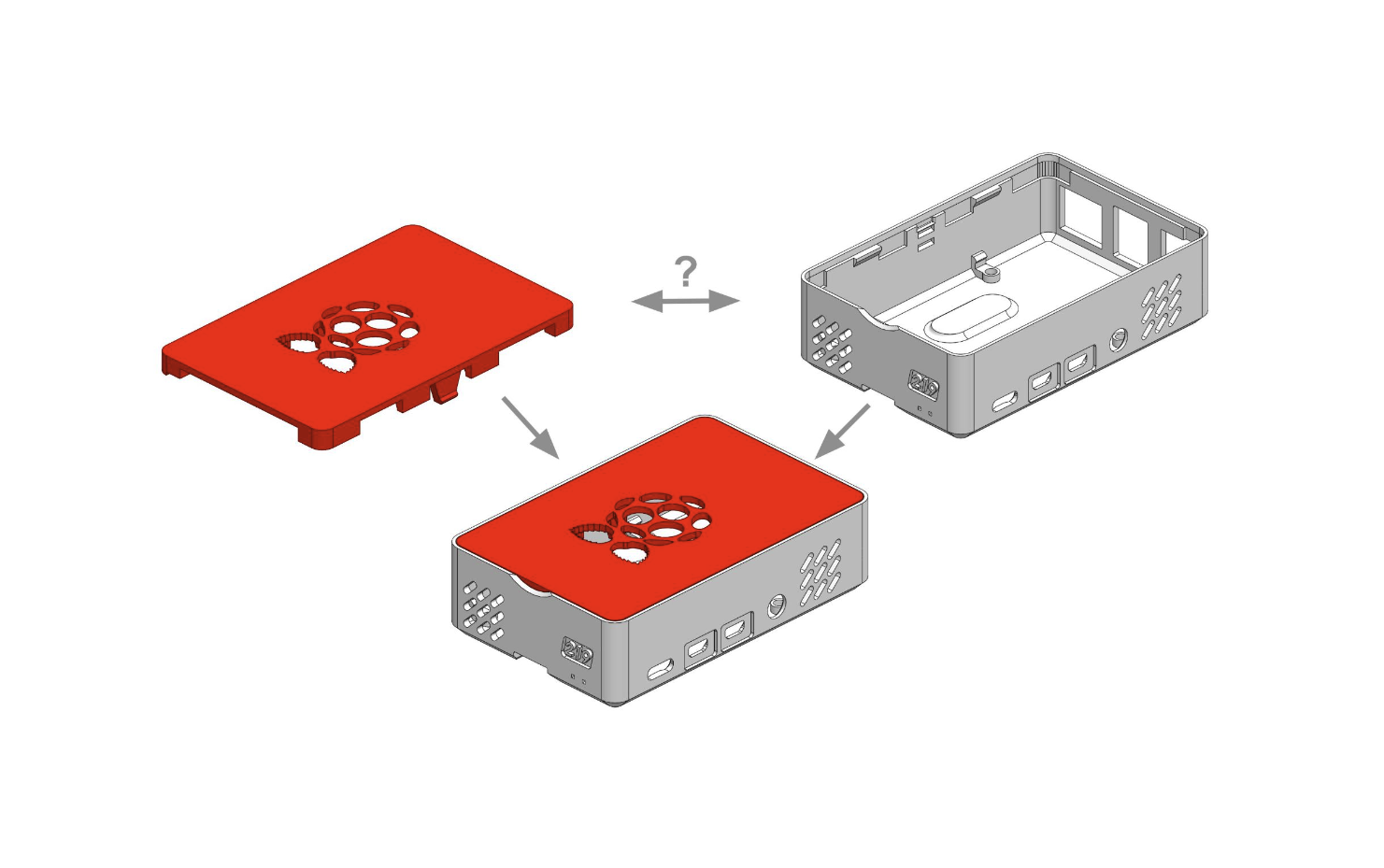
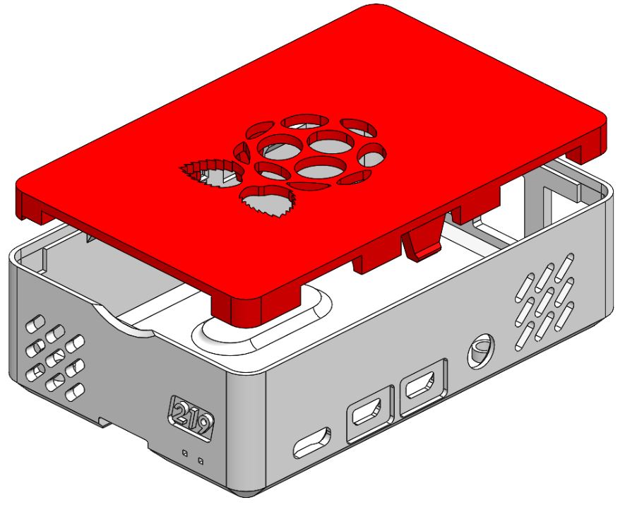
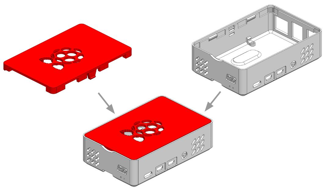
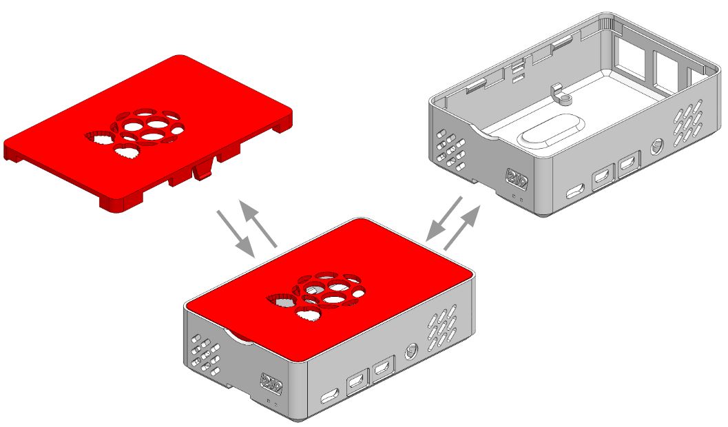
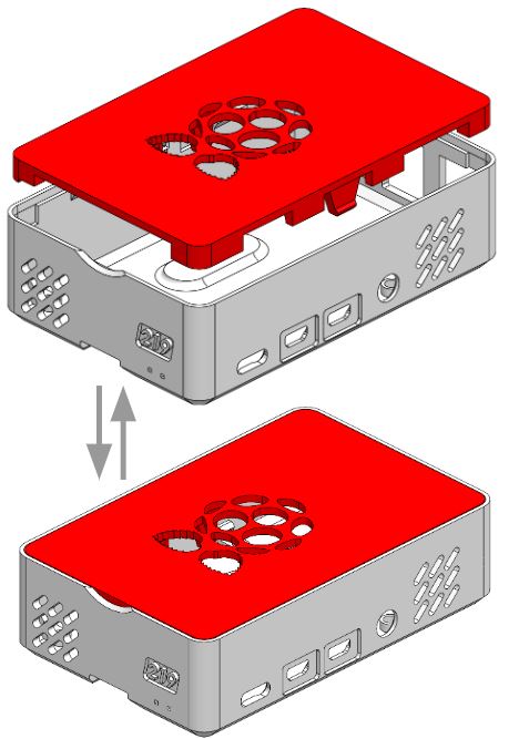
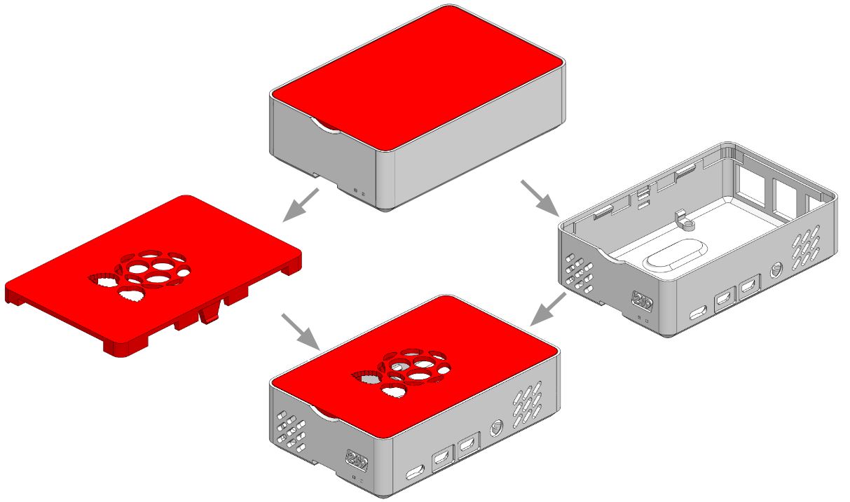
Our Raspberry Pi Case from a past blog post helps illustrate a multi-part design scenario, a ‘case study’ if you will. The case has two part bodies: the top lid (red) and the bottom shell (grey).
The naive, default process would be to make the lid as a part, the bottom shell as a separate part, and combine them in an assembly.
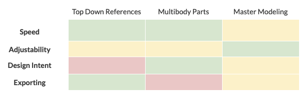
As designers and engineers, we want the edge of the lid to line up with the edge of the shell, and to continue to correctly line up while we iterate through designs. We can leverage CAD software to automatically update one part based on the other, but each approach also has drawbacks. To compare alternative multi-part design methods, we considered trade-offs in the following categories:
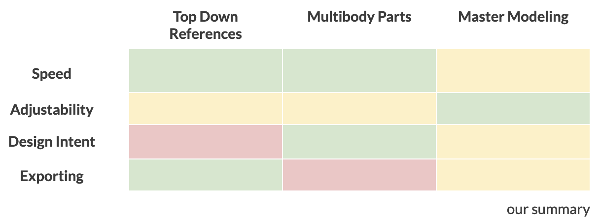
- Speed – How fast is it to create our CAD models?
- Adjustability – How easy is it to make changes to the geometry of our interfacing parts? In our example, if we changed one dimension on the bottom shell, do we have to go to a different part file to make the change?
- Design Intent – How easy is it for others to understand our design in CAD? When a teammate or client looks at our CAD model, we would like them to easily understand why we chose each aspect. “Ah yes, the lid is 1mm wider because it matches the bottom shell.”
- Exporting – On a bill of materials, do we want the shell and lid to show up as separate line items or as a single case? Could we send the lid file on its own to a manufacturer or would we need to include the whole assembly?
Preferred Methods
Courtney’s Preference: Top Down References
“Part to part references are handy when features are closely tied to each other. “
-Courtney
When combining parts together in an assembly, it’s common to use part-to-part references, also known as “Top Down” modeling or in-context editing. These changes are made from inside the assembly file. For example, you could change the groove of the grey shell to match the snap of the red lid.
This method is probably the most well-known and easiest to implement. It can be used with custom or off-the-shelf parts. However, it has its drawbacks. It’s fast when setting things up initially, but problems can come when changes need to be made much later. Since parts are referenced off of each other, unrelated changes to a part geometry can cause cascading issues with the part-to-part references, as well as the assembly as a whole. Design intent can be somewhat difficult to understand as well, as a referenced feature will show up on the part as an ‘external reference’ without much additional context. On the other hand, this method is great when it comes to exporting. Since every part is its own file, every part shows up as an individual entry on a bill of materials (BOM).
Use when: working fast, working with off-the-shelf parts, or on simple references
Abe’s Preference: Multi-body Parts
“When I’m prototyping, I’ll make multiple bodies in the same part file to move fast.”
– Abe
This method is similar to normal part-to-part references in an assembly. However, the key difference is that these references and parts are created inside the same part file, rather than the assembly.
The multi-body part method is a good “go-to” method because it offers a balance of speed, adjustability, and design intent – but has a few disadvantages. The primary disadvantage is when it comes to exporting, as one part should correspond to only one part number on a BOM. Additionally, in Solidworks, creating multiple bodies at the part level means that in the assembly, the parts will be static instead of having dynamic mates. Finally, a good thing to keep in mind is that using the multi-body part method gets more complex as the amount of parts increases. It may be best to break up assemblies with lots of parts into multiple multi-body parts, or a multi-body part can transition to be the master file in a master model process.
Use when: designing small numbers of parts with lots of references but no relative motion.
Trevor’s Preference: Master Modeling
“I never use part to part references, outside of master models, as they are fraught with circular references and are very difficult to diagnose when they fail.”
-Trevor
The master modeling method involves starting with the creation of a separate part that will serve as the “master model” or “skeleton” for the entire assembly. The master model will have geometry for all the references, though not the full detail of each part. Each individual part then inherits or “derives” the master model and thus the reference geometries.
The master model method works well with large numbers of parts, as changes can be applied to the “skeleton” part and update multiple parts within an assembly without cascading issues. The main disadvantages come from the need of the additional “master model” part as well as the foresight required to implement this method at the beginning of your design process. In addition, the design intent may not be as easy to understand by people not familiar with this method.
Use when: making complex assemblies
Final Considerations
Multiple methods can accomplish the same task, but it’s important to know the strengths and weaknesses of each method. With a simple multi-part design such as our Raspberry Pi case example, there may not be much additional benefit gained from one design method compared to another, but as the complexity of assemblies grows to dozens of related but independent parts, the trade-offs become more impactful.
Summary Chart
Onshape
In this blog, we have assumed the use of Solidworks, but other CAD programs have slightly different tradeoffs. For example, in the newer cloud-based Onshape CAD software, top-down references will instantly update. Onshape can also have dynamic assemble mates from multi-body parts. Both top-down and multi-body approaches are thus a more appealing choice in Onshape.
Though we presented them here as starkly separate, each of our engineers employs a combination of approaches. We have links below of other folks’ take on this same topic. We would love to hear your considerations when linking up parts. If you would like to link up with us, send us an email at getstarted@219design.com.