Optimizing Product Design
Raspberry Pi CM4
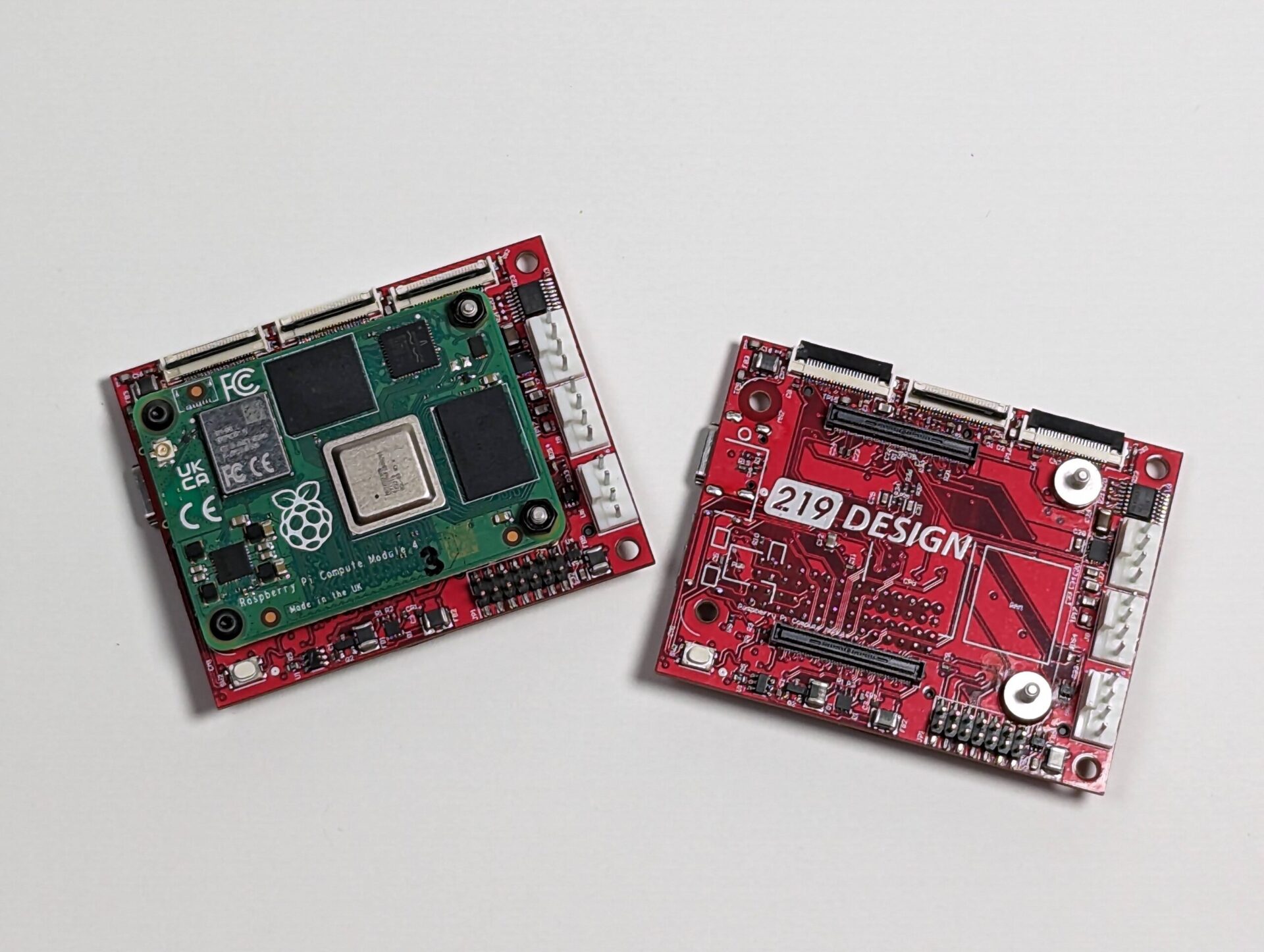
If you’re using a Raspberry Pi in your product design, it might be time to consider upgrading to the Raspberry Pi Compute Module 4 (CM4) paired with a custom carrier board. Unlike traditional Raspberry Pi boards, the CM4 offers a more streamlined solution. It’s perfect for creating compact, efficient designs tailored to your needs.
Raspberry Pi products are beloved by hobbyists and professionals for their versatility, open-source designs, and community support (among other reasons). However, standard development boards like the Raspberry Pi 4 often include numerous peripherals that may not be necessary for your application. While this flexibility is invaluable during development, it can pose challenges when transitioning to a final product design.
The RPi CM4 IO board serves as the standard development platform for the Compute Module 4, breaking out all available peripherals. However, its large size can be a drawback, especially when designing compact prototypes or consumer-ready products.
Fully Custom vs. System-On-Module
At 219 we can help you navigate the decision-making process between a fully custom board and a system-on-module approach. Whether it’s selecting the right system for your needs or designing custom carrier boards based on your priorities, we’re here to assist. To address the challenges of the CM4 IO board’s size we’ve developed a compact, full-featured carrier board. This smaller alternative retains all the essential peripheral functionality of the CM4 IO board while significantly reducing its footprint. Our carrier board was also designed to be modular, which allows additional boards to be stacked on it for more or adapted functionality. See the table and image below for a detailed size comparison.
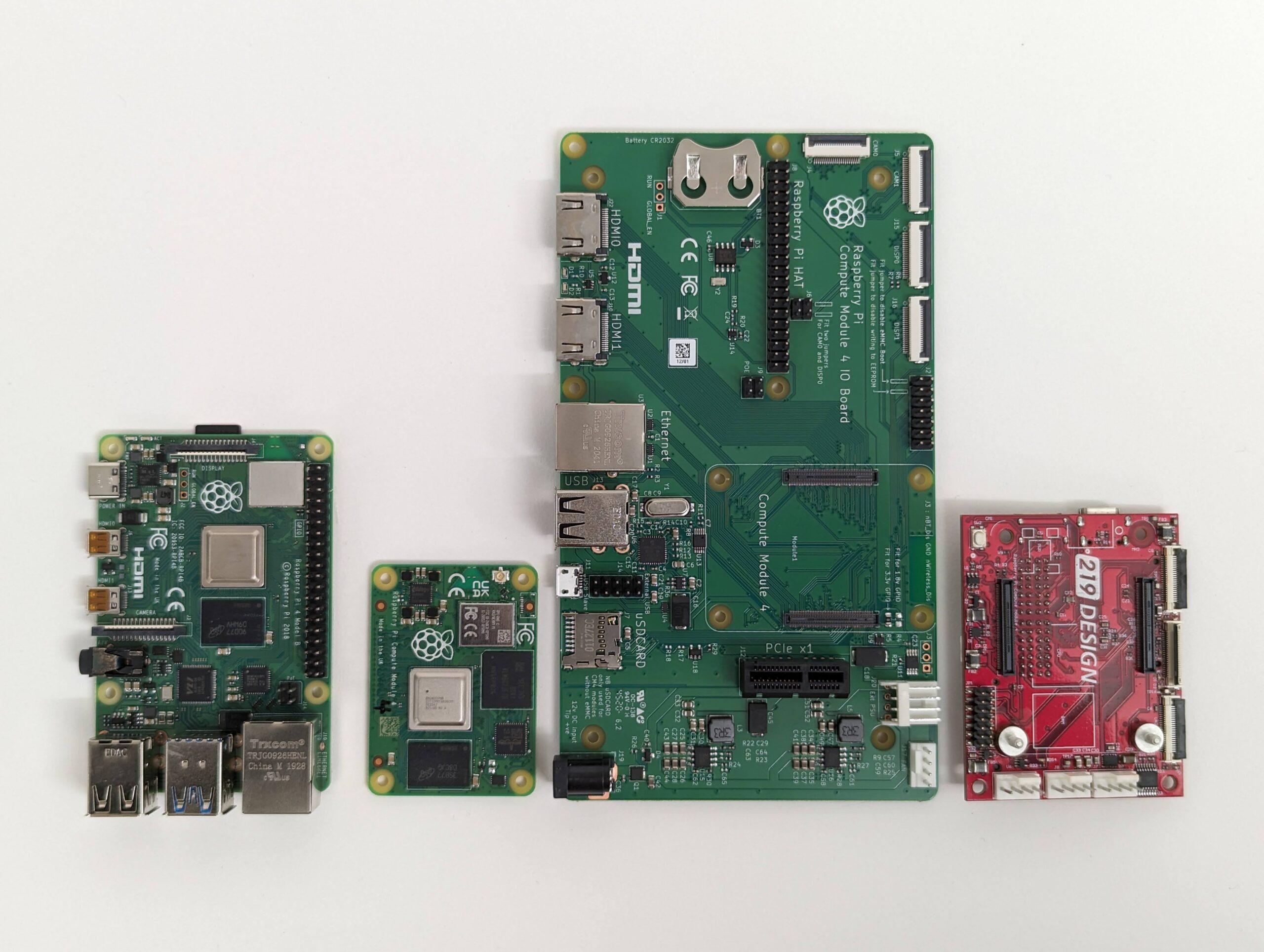
Size Comparison Table
Listed in the same order as the above picture, left to right:
| RPi 4 | CM4 | CM4 IO Board | 219’s CM4 Carrier Board | |
| Dimensions (mm, W x L x H) | 85 x 56 x 17 | 55 x 40 x 4.7 | 160 x 90 x 18.6 | 53 x 67 x 16.4 |
Introduction to 219’s RPi CM4 Carrier Board
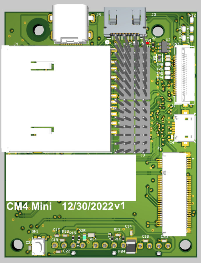
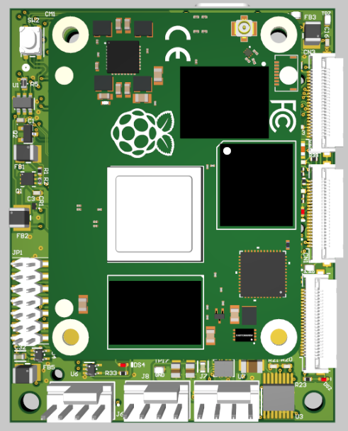
Our RPi CM4 carrier board provides the essential peripherals from the CM4 while maintaining the compact design of the module. This board serves as a starting point, and 219 can customize it to meet the specific needs of your product. Below is a comprehensive list of the key features of our carrier board.
Feature List
- Socket for direct connection of an RPi Compute module 4
- USB-C (Power-only)
- USB (Single OTG micro-B port)
- Mini-HDMI
- LEDs (2 GPIO, activity, CM4 Power, SD Power, IO Power)
- User pushbuttons (2)
- SD card (Full size, smaller sizes are supported with an adapter)
- MIPI (2 DSI, 2 CSI flex connectors)
- PCIE (M.2 B key)
- Fan controller with thermal inputs (2) and fan outputs (2)
- Stackable design with headers for GPIO, UART, SPI, I2C, and other low-level signals and configuration
- Small form factor (53 x 67 x 16.4 mm)
Bringing Up 219’s RPi CM4 Carrier Board
Usually when we design a board we put together a bring-up test plan tailored to the design while the board is being fabricated and assembled. We start with a general checklist of considerations then go through each circuit and plan how it will be tested as well as pass/fail criteria. It is rare for the first revision of a custom board to not have any design issues, but it can happen (chance of no issues is inversely proportional to the board’s complexity). Below is a high-level overview of our bring-up procedure for this design along with a few issues that we ran into.
| Step # | Test Name | Bring Up Procedure (Bring Up Notes) |
| 1 | Power/Smoke Test | Power the board with a benchtop power supply at 5V and the current limit all the way down. Apply power, and slowly turn up the current limit to make sure there aren’t any shorts. Once the rails are up measure them. Ensure the three red LEDs turn on (CM4 power, SD power, IO power). If good then remove the bench power supply and repeat the measurements with a 5V 3A+ USB C cable into the USB C port. |
| 2a | Load Image Test | Flash the full 64-bit RPi OS image to the onboard eMMC following these steps. The steps call out jumping two pins together to disable eMMC boot. This test is only done on CM4s with an onboard eMMC. The CM4 Lite does not have an onboard eMMC, so skip this test if using a CM4 Lite. Power supplies with not enough current will prevent a successful boot (must be at least 3A). |
| 2b | SD Card Test | Flash the full 64-bit RPi OS image to an SD card and insert it into the SD card slot. This test is only applicable to CM4 Lite modules. Initially, we designed the SD card slot to function with all CM4 variants, intending it to serve as additional storage for modules equipped with onboard eMMC. However, CM4 modules with built-in eMMC internally use the external pins that would otherwise connect to the SD card. As a result, those pins are unavailable, and the SD card slot is functional only with CM4 Lite modules. During the bring-up process, we discovered that a necessary pull-up resistor was missing on the enable line for the SD card’s external power switch. Without this pull-up resistor, the CM4 Lite was unable to boot. After performing some quick rework to add the resistor, the SD card functionality was successfully restored.  |
| 3 | Boot Test | Plug a monitor into the mini HDMI port. Power the board and the OS should boot and ask for setup information. |
| 4 | Keyboard/Mouse Test | Hook up a mouse and/or keyboard to the micro USB connector. Ensure mouse and keyboard work while the board is booted. Note: The USB and HDMI ports are the only ports/connectors that support hot plugging. |
| 5 | GPIO LED Test | Write a Python script to toggle the GPIO lines that have connected LEDs. Watch the LEDs flash to verify functionality. |
| 6 | Button Test | Write a Python script to print some text after the button is pressed. Run it and ensure the text is printed after the button is pressed. |
| 7 | General GPIO Test | Using a Python script or the raspi-gpio command, configure the GPIO pin as an output and set its state to either high or low. Use a multimeter to measure the GPIO pin and verify that its state matches the programmed value. Toggle the pin to the opposite state and confirm the output changes accordingly. Repeat this process for all GPIO pins not allocated to other tested peripherals. |
| 8 | CSI Test | Hook up a 15-pin MIPI camera to the CM4 Carrier Board via an RPI 5 camera cable. Add the necessary lines to the config file to enable CSI. Test using the rpicam-app rpicam-hello. Test both CSI ports. We discovered that the pinouts for the CSI and DSI connectors were reversed, with pin 1 actually aligning with pin 22 compared to the CM4 IO board or the Raspberry Pi 5. To test the design before making corrections for the next iteration, we created a makeshift cable by soldering together a Raspberry Pi 5 camera cable and a 22-pin Type A FFC. This improvised solution allowed us to verify that the design was fully functional once the pinout was corrected.  |
| 9 | DSI Test | Hook up the Raspberry Pi 7” touch display to the CM4 carrier board via an RPi 5 display cable and externally power the display via the micro USB port on the display. Add the necessary lines to the config file to enable DSI. Reboot the CM4 and see the touchscreen show the booted OS. Test both DSI ports. The DSI ports had the same pinout issue as the CSI ports, so we created a similar adapter cable to conduct initial testing before updating the design for the next iteration. |
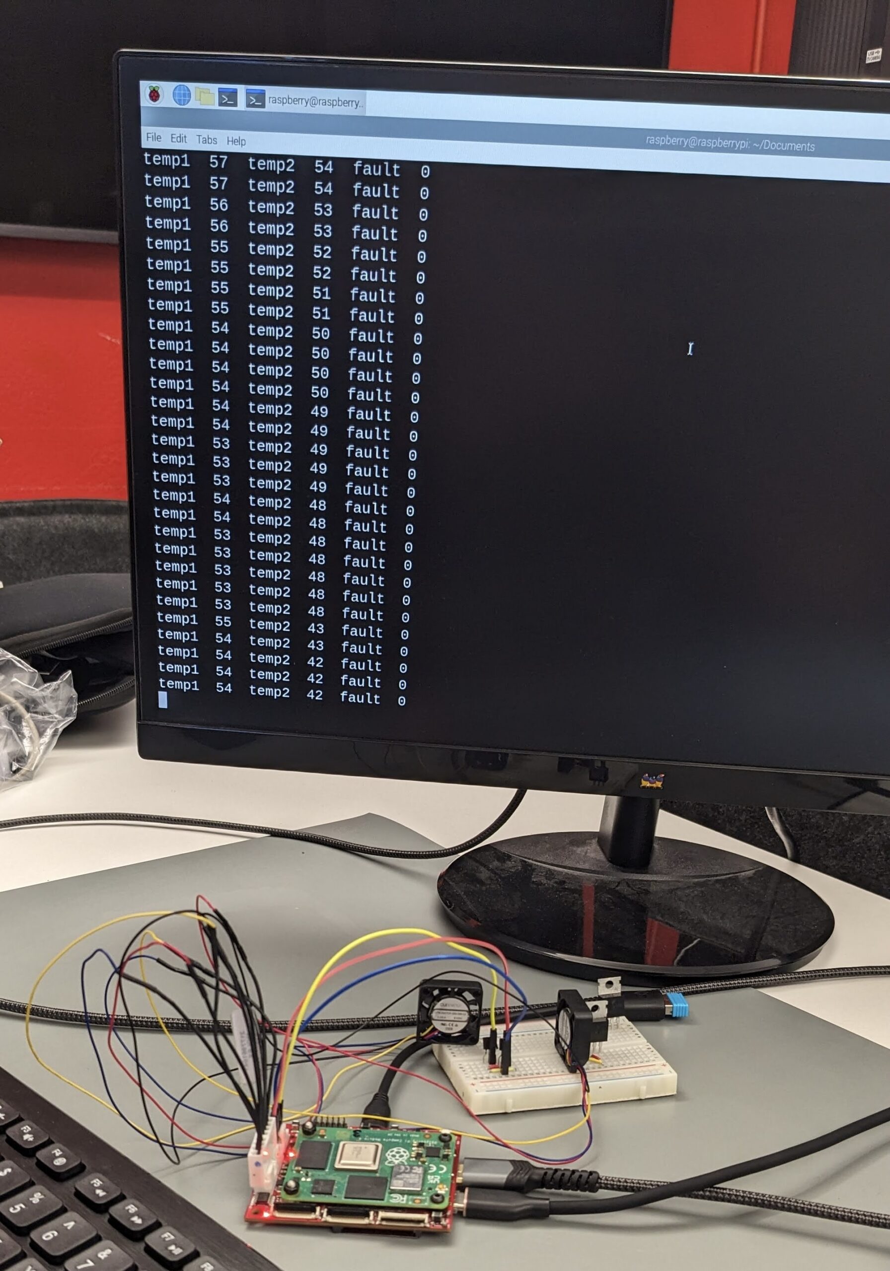
| 10 | Fan/Thermal Input Test | Hook up BJTs to the thermal inputs and 4 pin PWM fans to the fan outputs. Determine which I2C bus and address the thermal controller chip is on. Write a Python script to set the necessary I2C registers to put the controller chip in Auto RPM mode. Test to ensure the fan turns on when the temperature is above the set temperature and turns off when the sensor reading drops below the set level. The MAX6639 thermal controller chip has a kernel driver. During bring-up we discovered that the driver was not by default available on the RPi OS image for the CM4 and we ran into issues loading the kernel module manually using modprobe. To work around this, we opted to write a Python script to configure the I2C registers. Determining the correct register settings for our use case proved time-consuming. The quick start guide in the datasheet was geared toward a fan controlled externally by a FET, while our carrier board was designed for a fan with a built-in PWM controller. Additionally, we had to change the GPIO pin functionality from its default state to an alternate configuration to enable I2C. While this might seem straightforward, it was nonintuitive because the MAX6639’s correct address was visible under i2cdetect even when the pin functionality wasn’t properly set to I2C. |
| 11 | PCIE Test | Plug a PCIE device into the connector and secure it. Boot the CM4 and run lspci to ensure the device enumerates. During bring-up, we discovered that the RX and TX pins on our carrier board were swapped. To verify functionality before placing a new board order, we performed detailed rework to correct the pin assignment. After the rework, the PCIe modules successfully enumerated, confirming the design’s functionality. 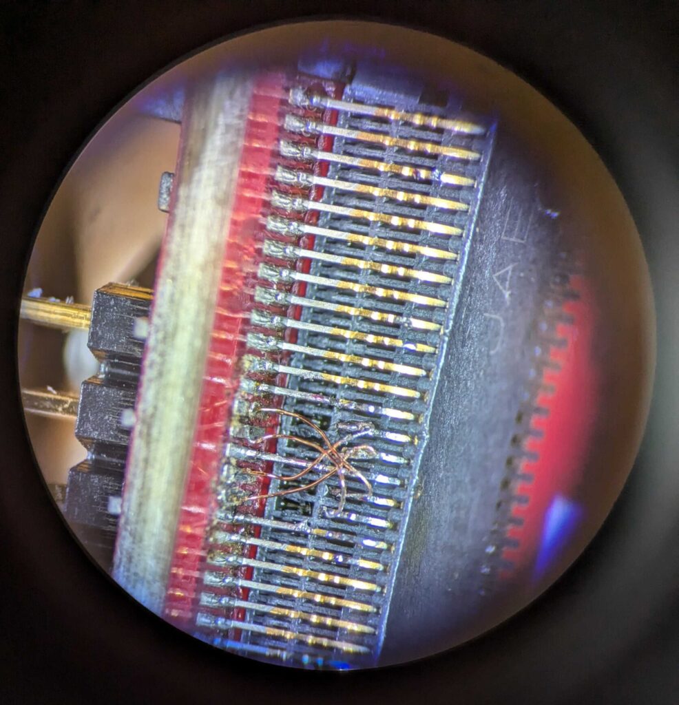 |
| 12 | UART Test | Hook up the UART pins to a computer via a serial cable such as a TTL-232R-3V3. Enable UART in the config file. Write a Python script on the CM4 to print out data over the serial port. Open a serial terminal on the computer and ensure the data printout appears. A loopback test could also be done on the board. |
| 13 | SPI Test | Hook up an Aardvark I2C/SPI Host Adapter to the SPI pins as a slave device and enable the SPI bus in the config file. Write a Python script to send SPI data and ensure it prints out the response message sent by the Aardvark. An on-hand eval board or dev kit with a SPI sensor could be used as well, or an Arduino if an Aardvark is not available. |
| 14 | I2C Test | Set the GPIO pins to the corresponding alternate mode for I2C mode. Hook up an Aardvark I2C/SPI Host Adapter to the I2C pins as a slave device and enable the I2C bus in the config file. Write a Python script to send I2C data and ensure it prints out the response message set by the Ardvark. An on-hand eval board or dev kit with an I2C sensor could be used as well, or an Arduino if an Aardvark is not available. |
| 15 | Analog Input Test | Hook up a variable power supply set around 1.5V with a low current limit to one of the analog input pins. Slowly vary the voltage (don’t exceed 3V) while reading registers 0x1C and 0x1D over I2C. During testing these pins were found to not be supported by the CM4 with a default configuration of the RPi OS that we used (reference). |
Why Use 219’s CM4 Carrier Board?
Out-Of-The-Box
219’s CM4 Carrier Board could be a good fit for a client’s design, as it’s only slightly larger than the CM4 itself. This makes it an excellent “out-of-the-box” development board that works well in a compact form factor.
Customizable
Additionally, our carrier board offers flexibility for custom add-ons. If the form factor is right but additional functionality is required—such as PoE, extra HDMI ports, or a MIPI breakout—we’ve included pins on stackable connectors to easily expand.
Accelerate Development
Are you working on an application with a Raspberry Pi Compute Module? Do you want to accelerate your design with our CM4 carrier board, or with a customized version? We’ve already done the groundwork, allowing us to create your custom board faster, more efficiently, and with fewer revisions compared to starting from scratch. Reach out to us at getstarted@219design.com.
Our electronics expertise encompasses so much more than carrier boards! Check out our Selected Work page. Lastly, check out our open-source 3D printed RPi 4 case blog post if you are looking to stick with your RPi 4 but need a cooling case.
